loader

8051-Microcontroller Trainer

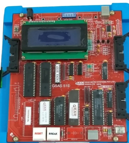
8051 family of microcontrollers and its derivatives are increasingly becoming popular for Instrumentation and control applications due to its speed and powerful instruction set which are essential for real-time applications. This has created the need for a good trainer and development tools. 51E (a low cost version of 51) provides a complete solution for this requirement. It can be used as flexible instructional aid in academic institutions and a powerful development kit in R&D Labs. The system firmware provides standalone monitor, serial monitor, one line assembler, disassemble and drivers for EPROM programmer and parallel printer interfaces. 51E is supplied with comprehensive and user friendly documentation as well as windows based communication software with online-help.
MAIN FEATURES
  • 51E operates on single+5V power supply either in stand-alone mode using PC keyboard and LCD or with host PC through its RS-232-C interface in serial mode.
  • Stand-alone and serial monitor programs
  • support the entry of user programs, editing and debugging facilities like single stepping and full speed execution of user programs.
  • On-board 20× 4LCD Module.
  • Total on-board memory is 128K byte of which 88K bytes RAM has battery backup provision.
  • 48 1/O line and four programmable interval timers.
  • 9 port line of MCU brought out to the right angle ribbon cable connector including INTI.
  • Buffered Bus Signals are available through ribbon cable connector for easy system expansion.
  • Driver software for file upload/download to/from host PC.
  • ACCESSORIES (OPTIONAL
  • Power Adapter: ADP-DC5 (SMPS);+5V@3A
  • PC keyboard for stand-alone mode of operation.
  • EPROM programmer interface (2716 through 27512)
  • 8751 adapter for the above interface
  • Interface modules for training purpose: Keyboard, Elevator, Display, Dual DAC, 12 bit 8vchannel ADC, Logic controller, Traffic lights, Tone generator, stepper motor, Opto isolated input, Opto isolated Output, Relay output, DC motor interface, Temperature Controller interface, etc.,
  • Study cards for 8255,8279, 8251/8253, etc.,
  • Power supply:±5V @3A;± 12V @ 250mA; +30V @100mA (required for some of the above interfaces)
  • 3.6V Ni-Cd battery for power backup to RAM.
  • Parallel Printer cable.
  • SPECIFICATIONS
    MCU
  • 8031/51@11.0592 MHz.
  • MEMORY
  • Two JEDEC sockets provide following memory
  • Configuration
  • ROM: 32K bytes of system firmware using 27C256
  • RAM: 96K bytes, 32K bytes of program memory (using upper half of 628128) and 64K bytes of data memory (using lower half of 628128). Upper most 8K bytes of data memory are reserved for 1/O addressing and 1/O expansion.
  • PERIPHERALS
  • 8155: Static HMOS 256 byte RAM with I/O ports and timer. RAM reserved for monitor, 14 Bit Timer is available for user and port lines are used for LCD & system configuration.
  • 8255: PPI, Two Programmable peripheral interface devices; one supplied; another for user expansion one of them can be used for parallel printer interface one supplied; another for user expansion. One of them can be used for parallel printer interface.
  • 8253: PIT, programmable interval Timer. Three 16 bit Programmable timers available for user.
  • 8042: UPI, Universal Peripheral interface used to interface PC keyboard in standalone mode.
  • INTERRUPTS
  • External: INT0 is used for single stepping and user’s BREAK key. INT1 is available to user.
  • Internal: Internal timer and serial interrupts are used by the system monitor
  • .
    INTERFACE SIGNALS
  • MCU Bus: Bus signals are available through two 26 pin right angle flat ribbon cable connectors
  • Parallel 1/O: 48 TTL compatible lines (2× 8255) brought out through two 26 pin right angle flat ribbon cable connectors
  • Serial 1/O: RS-232-C through on-board 9 pin D-Type female connector
  • Timer signals: Three 8253 and one 8155 timer signals are available at the 26 pin right angle flat ribbon cable connector
  • GENERAL
  • Power Supply Requirement: + 5v @ 0.9A (approx). Dimension: (L) 240mm × (B) 210mm × (H) 50mm (approx). Weight: 700grams (approx).
  • Housed in an ABS plastic moulded cabinet.
  • SCOPE OF SUPPLY
  • 1. 51E Trainer with 20X×4LCD.
  • 2. User’s Manual.
  • 3. Drivers software (CD) for Windows and DOS..
  • 4. 8051 Reference Card.
  • 5. RS-232-C cable.
  • 8085 MICROPROCESSOR TRAINER-85E

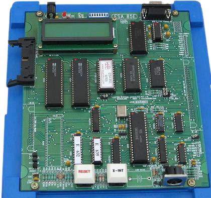
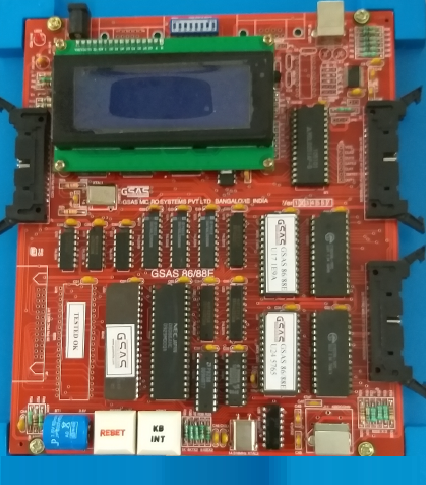
    85E is the economy model of MPS 85-3 Microprocessor trainer based on the popular 8085 CPU with onboard LCD and PC connectivity through its RS-232-C port. 85E can be used as flexible instructional aid academic The system firmware provided stand alone mode monitor, serial monitor, single line assembler and dis-assembler 85E is supplied with comprehensive and user-friendly documentation along with windows drivers to communicate with host PC.


    MAIN FEATURES:
  • 85E operates on single +5V power supply either in stand-alone mode using PC keyboard and LCD or with host PC through its RS-232-C interface in serial mode.
  • Stand-alone and serial monitor programs support the entry of user programs, editing and debugging and full speed execution of user programs. Single Line Assembler & Dis-assembler support in both stand-alone and serial modes of operation. 32K Bytes of CMOS static RAM is provided with battery backup option. Allows multi-Processor system design by supporting the HOLD and HLDA Signals 48 I/O lines and 3 Programmable interval timers.
  • Driver Software for file upload/download to/from host PC.
  • : ACCESSORIES (OPTIONAL)
  • Power Adapter:+5V@2A(SAMPS)
  • PC Keyboard for stand –alone mode of operation
  • EPROM Programmer interface(2716 through 27512)
  • Interface Modules for training purpose(Keyboard,Elevator,7Segment Display,ADC with DAC,Dual Slope,Logic Controller,crystal clock Divider,traffic Lights,RTC,Tone generator,Stepper motor etc.,)
  • Power supply:+5V@3A:±12V@250mA:and +30V@100mA (required for some of the above interfaces).
  • 3.6V Ni-CD battery for Power backup to RAM .
  • SPECIFICATIONS
    CENTRAL PROCESSOR UNIT :
  • CPU:8085@3.072
  • MEMORY:
  • Two JEDEC 28 Pin sockets provided the following memory configuration
  • ROM: 16K bytes using 27128 or 32K bytes using 27256.The system firmware is supplied in 27128EPROM.
  • RAM: 32K bytes using 62256.
  • PERIPHERALS:
  • 89C2051:MCU used to interface with PC keyboard in stand alone mode of operation
  • 8251A: Programmable communication interface for serial communication supporting standard bauds from 110to9600
  • 8255A: Three Programmable peripheral interface devices, Two Nos. for user; one supplied, another for user expansion (Optional). Remaining one is used for LCD and System configuration
  • 8253: Three Programmable interval timers: Timer 0 is used for single step, Timer 1 for baud clock generation and timer 2 is available for user.
  • INTERFACE SIGNALS:
  • CPU Bus: De multiplexed, buffered and non-buffered, TTL Compatible Signals are terminated on 50 pin ribbon cable connector
  • Parallel1/O: 48 TTL Compatible I/O lines (2×8255) brought out through two 26 pin ribbon cable connectors
  • Serial 1/O : RS-232-C through on-board 9 Pin D-type female connector.
  • Timer Signals: All three timer signals are brought out to J3 header .
  • GENERAL:
  • Power supply
  • requirement: +5V @0.8A (approx)
  • Dimensions: 230mm × 270mm × 45mm (L×B×H.)
  • Weight: 700gms. (Approx)
  • House in ABS plastic molded cabinet
  • SCOPE OF SUPPLY:
  • 1. 85E Trainer
  • 2. RS-232-C Cable
  • 3. 85 Driver Software CD.
  • 4. User’s manual with schematics.
  • 5. 8085 Assembly Reference card.
  • 16-BIT MICROPROCESSOR TRAINER-86/88E

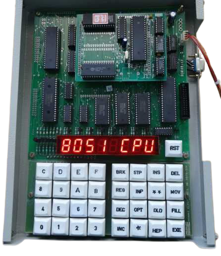
    86/88E is an economical version of our advanced microprocessor trainer 86/88-3. It is a powerful, general purpose microprocessor trainer which can be operated either with 8086 CPU or 8088 CPU at a clock frequency of 5MHz in maximum mode of operation. It has provision for on-board NDP (Numeric Data Processor) 8087. It configured for different modes of operation using DIP switch settings. The basic system can be expanded through the system bus connector. The powerful firmware provides keyboard monitor, serial monitor, one-line assembler, disassemble and driver programs for parallel printer interface and PROM programmer interface. 86/88E is supported with comprehensive and user-friendly documentation. 86/88E can communicate with a PC compatible host system using the DOS/window based Driver Software supplied along with the trainer. All the standard commands of the serial monitor of 86/88E are fully supported by this package with online help. In addition, object code files (HEX files generated using PC native tools like MASM, TASM) can be downloaded to 86/88E from the host computer system, permitting the development of powerful application software. All these features make 86/88E a complete single board microcomputer for development in R&D labs and industries or for training in research and educational institutions.
    MAIN FEATURES:
  • 86/88E operates on single +5v power supply either in standalone mode using PC keyboard and LCD or with host PC through its RS-232-C interface in serial mode.
  • Work with either 8088 CPU at 5MHz
  • Provision for on-board 8087 NDP
  • Keyboard and serial monitor programs support the entry of user program, editing and debugging facilities like breakpoint, single-step and full speed execution of user program.
  • Built-in One Line Assembler, Disassembler in both serial and stand-alone modes of operation
  • 86/88E has provision for on-board memory of 192K Bytes inclusive of 64K bytes of RAM with optional battery backup.
  • Monitor resident parallel printer driver
  • 48 1/O lines and three 16-bit programmable interval timers.
  • Provision for system bus expansion through 50 pin ribbon cable connector
  • User friendly menu driven windows driver software for file upload/download to/from host PC
  • 64K Bytes of software breakpoints implemented through windows driver
  • ACCESSORIES (OPTIONAL):
  • Power Adapter: +5V@3A(SMPS)
  • PC keyboard for stand-alone mode of operation.
  • 8087 NDP programmer interface to program 2716 through 27512
  • Interface modules for training purpose: Calculator type keypad, HEX Keypad Elevator, Display, Dual DAC,12 bit 8 Channel ADC, Logic Controller, Traffic Lights Tone Generator, Stepper Motor, Opto isolated input, Opto isolated Output, Relay output, DC motor interface, temperature controller interface etc.
  • Study cards for 8255,8279,8251/8253,8259 etc
  • Power supply:+5V@3A:±12V@250mA:and +30V@100mA (required for some of the above interfaces).
  • 3.6V Ni-Cd battery for power backup to RAM
  • Parallel Printer interface Cable
  • SPECIFICATIONS
    CENTRAL PROCESSOR:
  • 8086/8088 @5MHZ (supplied with 8086)
  • CO-PROCESSOR:
  • 8087 NDP
  • MEMORY:
  • 4 JEDEC sockets provide the following memory Configuration
  • ROM: 128K bytes system firmware using 27C512 (64K×2)
  • RAM: 64K bytes using 62256 (32K×2)
  • PERIPHERALS:
  • 8255: PPI: Three nos. of programmable
  • Peripheral interface. (72 I/O lines) One 8255 used by system for mode selection and LCD Remaining two nos. are for user, one supplied; another for user expansion.
  • 8253: PIT; Programmable interval timer. Three16 bit programmable timers, timer 0 for baud, timer 1 and 2 available for user.
  • 8251: USART for serial communication
  • supporting all standards bauds From 110 To 19200.
  • 8042: Universal Peripheral interface used to interface with PC Keyboard in standalone mode
  • 8288: Bus Controller used to generate Control signals
  • 8284: Clock generator used to generate clock & RESET signals.
  • INTERUPTS:
  • External: NMI for user through KBINT key
  • INTR is left unconnected
  • Internal: INT1 for single step
  • INT3 to break user program
  • .
    INTERFACING SIGNALS
  • CPU Bus: De multiplexed and fully buffered, TTL
  • Compatible: Address, Data & Control signals are available on two 26 pin flat ribbon cable connectors.
  • Parallel1/O: 48 Programmable paralle1/O lines through two 26 pin ribbon cable connectors.
  • Serial 1/O: RS-232-C through on-board 9 Pin D-type female connector.
  • Timer Signals: Timer 1&2 signals are brought to a header.
  • GENERAL:
  • Power supply requirement: +5V @1.4A (approx)
  • Dimensions: (L)240mm × (B)210mm × (H)50mm (Approx.)
  • Weight: 700gms. (Approx)
  • House in ABS plastic moulded cabinet
  • SCOPE OF SUPPLY:
  • 1. 86/88E Trainer
  • 2. RS-232-C Cable
  • 3. DOS & windows Driver Software CD
  • 4. User’s Manual with Schematics
  • 5. MCS-86 Assembly Language Reference Card
  • Minmax-8085-MICROPROCESSOR TRAINER KIT

    MICR-8085 is 8 bit microprocessor. Trainer kit based on Intel’s 8085 microprocessor. It is an universal type kit with 8085 CPU Module plugged onto it. With Micro 8085 one can enter machine Coded programs, check their correctness, execute it and verify the results. It has on-board RS232 Interface to download inter-hex files from PC. The on-board peripherals of micro 8085 include 8255(Programmable Peripheral Interface), 8279(Keyboard/Display Controller), 8253(Programmable Interval Timer), 8259 (Programmable Interrupt Controller) 8251(Programmable serial Communication Interface) with RS232 drives 1488/1489. MICRO -8085 operate from 230V AC Through an external Power Supply Unit.
    SPECIFICATIONS: CPU : 8085A MEMORY : 8K RAM Expandable to 24K 32K EPROM (27256) DISPLAY : 8 digit 7 segment LED display KEYBOARD : 33Keys keyboard including RESET PARALLEL PORT : 2Nos.8 8255(Programmable Peripheral Interface) SERIAL PORT : 8251A (Programmable Communication Interface) TIMER : 3Nos. 16 bit Programmable Timer using 8253 INTERRPUT : 8259 Interrupt Controller SOFTWARE FACILITIES : Break, Single step, Execute, Register, Move, Fill input, out put,Download,Insert,Delecte Etc.
    EDUCATIONAL INTERFACE CARDS: The following is the list of additional interface card compatible with MICRO 8085 trainer kit. These cards are connected to 8255 Port lines through 26 Pin FRC cable extenders. ♦A to D Converter Using ADC0809 ♦Stepper Motor Controller ♦ Opto isolated digital input card ♦ 4 Channel Relav Card ♦D to A converter Using DAC0800 ♦Traffic Lights Simulator ♦ Opto isolated Digital Output Card, ♦ Hex Key pad Interface

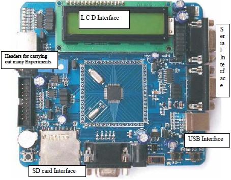
    PSOC BOARD

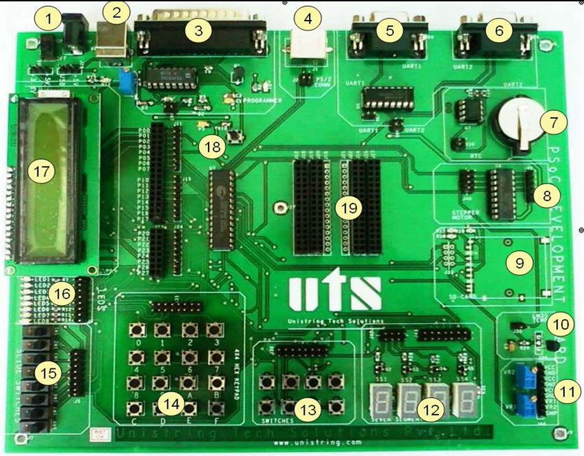
    SPECIFICATIONS: 1. Power Supply Jack 2. USB Power Supply 3. Parallel Programmer 4. PS/2 Connector 5. UART1 Connector 6. UART2 Connector 7. RTC 8. Stepper Motor Connector 9. SD Card Connector 10. LM35 Temperature Sensor 11. Potentiometer and Power 12. Seven Segment Display 13. Push Button Switches 14. Hex-Key Pad 15. Slide Switches 16. LED Display 17. LCD Display 18. Reset Button 19. Bread Board Connector
    8051-MICROCONTROLLER TRAINER

    ARM BOARD

    SPECIFICATIONS:  LPC2148 ARM7TDMI-S, 16- bit(THUMB)/32-bit(ARM) ARM7TDMI-S microcontroller.  512 KB high speed flash memory,32 KB On-chip ram, 128 bit wide interface/accelerator enables high speed operation  On chip PLL which  Serial Port to connect to PC.  On board voltage regulator  On chip multi channel ADCs  On chip DAC

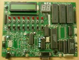
    8051 BOARD

    SPECIFICATIONS:  PHILIPS P89C51RD2 microcontroller (64 KB Flash, 1 KB data memory etc, Please refer to the data sheet)  11.0592 MHz clock frequency  Push button switches -8  Slide switches -8  Serial communication link with RS-232 level translator  Two Seven Segment Display  Eight LEDs  In System Programming feature  ADC  DAC  Power adaptor and serial cable

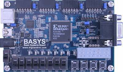
    FPGA BOARD FOR ECAD LAB

    SPECIFICATIONS:  Xilinx Spartan 3-E FPGA, 100K system gates  FPGA features 18-bit multipliers, 72Kbits of fast dual-port block RAM, and 500MHz+ operation  USB 2 port for FPGA configuration  XCF02 Platform Flash ROM that stores FPGA configurations indefinitely  User-settable oscillator frequency (25, 50, and 100 MHz), plus socket for a second oscillator  Three on-board voltage regulators (1.2V, 2.5V, and 3.3V) that allow use of 4V-9V external supplies (power supply included)  8 LEDs, 4-digit seven-segment display, 4 pushbuttons, 8 slide switches, PS/2 port for mouse and keyboard experiments,3-bit VGA port for graphics driver experiments  Four 6-pin headers for user I/Os for attacing external modules

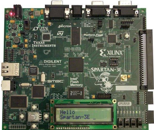
    FPGA BOARD FOR SIMULATION LAB

    FPGA_BOARD_FOR_SIMULATION SPECIFICATIONS: Devices and Key features of this board  Xilinx XC3S500E Spartan-3E FPGA(5 lakh system gates on FPGA, 232 user I/O pins)  Xilinx 64-macrocell XC2C64A Cool Runner CPLD  Xilinx 4 Mbit Platform Flash configuration PROM  64 MByte (512Mbit) of DDR SDRAM  16 MByte (128Mbit) of parallel NOR Flash  16 Mbits of SPI serial Flash  SHA-1 1-wire serial EEPROM for bit stream copy protection  Four-output, SPI-based Digital-to-Analog Converter (DAC)  Rotary-encoder with push-button shaft  Four slide switches  PS/2 mouse or keyboard port  VGA display port  10/100 Ethernet PHY (requires Ethernet MAC in FPGA)  Two 9-pin RS-232 ports (DTE- and DCE-style)  Hirose FX2 expansion connector, Three Digilent 6-pin expansion connectors

    PIC MICRO CONTROLLER DEVELOPMENT BOARD-16FC

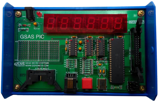
    PIC 16F8XX series of MCU from Microchip provided high performance, low cost and small package size. Offering the best price/performance ratio in the industry. These MCUs are used mainly in cost sensitive consumer products. Computer peripherals office automation, automotive Control systems, security and telecommunication application. GSAS PIC is a microcontroller development board based on PICF877 developed by sarayu infotech solution Pvt Ltd. IKt can be used as a flexible instructional aid in academic institutions and as a powerful development tool in R& D labs and industries engaged in microcontroller based system development.

    GSAS PIC is supported with MPLAB IDE for developing the user applications source in assembly language with the HITECH C complier(PICC) Software, the user can develop programs in C language can be downloaded and debugged using the optional in-circuit debugger module(ICD).

    MAIN FEATURES:  GSAS PIC Operates on can be operates on +5V DC power Supply  Optional ICD module allows downloading of user programs to the board. Further it supports full speed execution of user programs. ICD enables the user to debug the programs through single-stepping and break points.  Assembly language programs can be developed using MPLAB IDE supplied along with the board.  24 I/O lines are terminated out to the 26-Pin connector.  6 Digits seven segment LED display are provided on board  RJ11 Six pin GSAS PIC Compatible interface modules are provided along with the relevant programs. ACCESSORIES (OPTIONAL):  Power Supply:+5V@3A;+12V@250mA and +30V@100mA(required for some of the GSAS interface modules)  Interface modules for training purpose :Keyboard, Elecator, Diplay, Dual DAC,12 bit 8 Channel ADC, Logic controller, Traffic lights, Tone generator, stepper motor, real time clock interface, Dual slope ADC, 16 Channel ADC interface etc.,  In Circuit Debugger with cable, Model: GSAS ICD  HITECH C Compiler(PICC) Software to interface with MPLAB IDE for developing programs in C SPECIFICATIONS: CONTROL PROCESSOR  PIC 16F877 MCU @4mHz MEMORY  Program Memory: 8K of on-chip flash memory  Data Memory: 360 bytes of Onchip RAM memory PHERIPHERALS Internal: 10-bit 8 channel on chip ADC3 On-chip programmable interval timer one of which can be used as oscillator source. I on-chip capture/compare/PWM(CCP) module. I on-chip i2c compatible master synchronous serial port MSSP module. I On-chip UART for serial communication supporting all standard bauds from 110 to 1920 256 bytes of on-chip Data EEPROM memory. INTERFACE SIGNALS Serial I/O: RS 232 through on-board 9 pin D-type female connector. INTERRUPTS Internal: Internal Timer, ADC, Capture/Compare/PWM and serial interrupts a total of 12 Internal Interrupts. External: RBO/INT is a available as external interrupts for user. Power Supply Requirement: +5V@25mA+9V@500mA SCOPE OF SUPPLY  GSAS PIC board  RS232 Serial cable for programming  User Mannual.

    INTERFACE MODULES

    We deal with a variety of interface modules useful for teaching/training/lab Use. Many of these modules are designed to be interfaced with the programmable peripheral interface device8255A. However, some of the modules are bus-based designes.Most of the interface modules are supplied in a standard plastic enclosure. Every interface module is accompanied by a user’s manual with provides detailed installation and operational instructions, theory of the interface and sample programs to illustrate different features of the module.1.

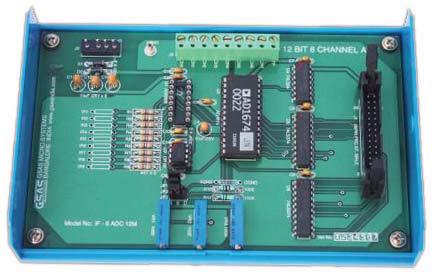
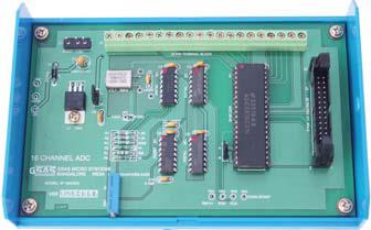
    12-BIT 8 CHANNELADC INTERFACE MODEL: IF-8ADC 12:

    This interface is based on analog device AD1674, ADC with 12-bit, 10µsec sampling rate.AD1674 has a built-in sample and hold amplifier too. The ADC accepts Unipolar (0-10V) or Bipolar (±10V or ±5V) Signal inputs. Provision for an optional 8 channel multiplexer, ADG508. The channels can be configured to accept current (4-20mA) or voltage signals. The interface has 9 pin terminal strip to feed the analog input voltages. This interface allows the user to become familiar with various applications of high precision ADC’s and analog multiplexer.
    2. 8-BIT 16-CHANNEL ADC INTERFACE (MODEL: IF-16ADC8):

    This interface provides 16-Channel, 8-bit ADC0816 – 16 channel 8 bit data acquisition device. Provision is made for on-board reference voltage generation using precision voltage regulator LM723.The interface has 20 pin terminal strip to feed in the analog voltages, the input signal voltage range is 0-5V

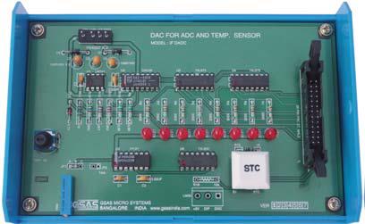
    3. DAC FOR ADC AND TEMP.SENSOR INTERFACE (MODEL: IF-DADC)::

    This interface consists of an 8-bit D/A Converter (DAC) and a comparator. User can control the input to the DAC through a port (the port output is latched and presented as input to the DAC).The DAC output and analog input are fed to a comparator whose output can be monitored through another port line. A key, whose status can be read through a port line, is also provided. User routine can read this key status to determine when to start the conversion. This interface allows the user to implement A/D conversion using DAC through successive approximation technique or counter technique. Also provides a simple temperature sensor simulator consisting of a TTL monoshot,allowing the user to employ a thermistor to convert a physical parameter like temperature to its equivalent digital code

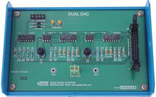
    4. DUAL DAC INTERFACE (MODEL: IF-DDAC):

    This interface consists of two 8-bit D/A Converters whose current outputs are converted to voltage output using operational amplifiers. These voltages (Ports Outputs) are available to the user. The inputs to the DACs can be controlled through I/O ports. A Sample program is provided with the interface to generate a triangular/square waveform. The waveform can be observed on CRO. The user can write separate programs to generate other wave forms like sine wave, sawtooth etc.

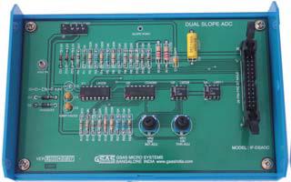
    5. DUAL SLOPE ADC INTERFACE (MODEL: IF-DSADC)

    This interface consists of an integrator and a comparator. A port line can be used to control a CMOS analog switch to reset the integrator, another port line can be used to control another CMOS analog switch to allow the integration of an analog input (the duration of integration is controlled by user software) and yet another port line can be used to control another CMOS analog switch to allow the integration of standard reference voltage (the duration of which can be measured by user software).The integrator output is fed to a comparator and the comparator output, in turn can be sensed through a port line. Offset trimming provision is available for the integrator and comparator. This interface helps the user to understand the principle of Dual slope ADC and to write software for implementing it and observe the switching waveforms

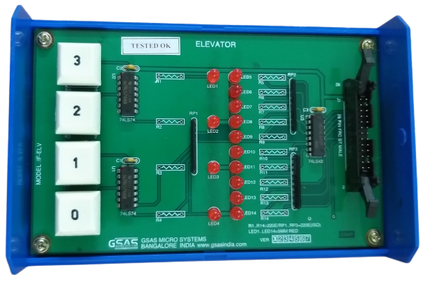
    6. ELEVATOR INTERFACE (MODEL: IF-ELV):

    This interface simulates the control and operation of an elevator. Four floors are assumed and for each floor a key and corresponding LED indicator are provided to serve as request buttons and request status indictors. The elevator itself is represented by a column of ten LED’s. The motion of the elevator can be simulated by turning on successive LEDs, one at a time. The delay between turning OFF one LED and turning ON the next LED can simulate the “speed” of the elevator. User can use different I/O lines to read the request status information, reset

    indictors and control the elevator (LED Column).The interface allows the user to write software for simulating the operation of elevator. The software exercise could include priority schemes, different service schemes, etc.
    7. KEYBOARD DISPLAY INTERFACE (MODEL: IF-KBD-DISP)

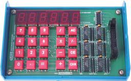
    This keyboard display interface provides a calculator style keyboard with seven segment displays. It consists of the switches 0 to 9, =, -, /, %, AC, CE, CHK and six 7-segment display. The 20 keys are arranged in a 4×5 matrix (each row has 5 keys). This interface allows the user to study a number of techniques generally used in calculator keyboard interfacing. User can write programs to gain a good understanding of keyboard display, arithmetic group of processor instructions by implementing the calculator functions (+, -, /, =, %, etc.)

    8. CALCULATE KEYPAD INTERFACE (MODEL: IF-KBD)

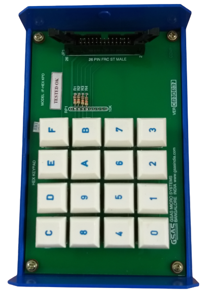
    This interface module provides a calculator style calculator keypad consisting of the switches 0 to 9, +, -, ×, =, %,.,.,C, CE, etc. These 20 switches are arranged in a 3×8 matrix (the third row has only 4 switches). The row lines can be driven through port C ( Bits PC2, PC1 and PC0) and the status of column lines can be read through port A. The interface allows the user to study a number of techniques generally used in calculator. User can write programs for software debouncing of key closures, two – key lockout, keyboard encoding and parsing etc., to gain a good understanding of keypad interface. User can become familiar with the processor’s arithmetic instructions by implementing the calculator functions like addition, subtraction, multiplication, division etc.,

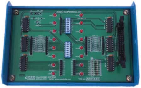
    9. LOGIC CONTROLLER INTERFACE (MODEL: IF-LC):

    This interface consists of eight TTL buffered outputs and eight TTL buffered inputs. The logic state of each input/output is indicated by a corresponding LED (ON/OFF). The inputs can be read through one port and the outputs can be controlled through another port. The input and outputs are brought to berg-Pins. Two Dip-Switches SW1 and SW2 are also provided. SW1 is used to connect the output status to the corresponding input line when the switch is ON. SW2 is used to set different logic states by setting the switch to ON (or) OFF. This interface allows the user to perform experiments to understand some of the basic programming techniques involved in a logic controller. The software exercises could include combinational controllers, Sequential controllers, Programmable counters etc..,

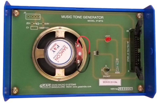
    10. MUSIC TONE GENERATOR INTERFACE (MODEL: IF-MTG):

    This interface consists of a transistor and a speaker. The transistor is driven by a port line and the transistor inturn amplifies the signal and drives the speaker. By controlling ON/OFF periods of the port line through software, user can generate the required musical note. Sample programs are provided to generate a variety of musical notes.

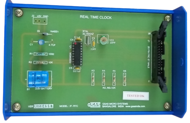
    11. REAL -TIME CLOCK INTERFACE (MODEL: IF-TRL):

    This interface is based on MSM 5832 real-time clock/calendar (RTC) Chip which can be interfaced to the I/O lines. The RTC is backed up by a battery, allowing it to retain all the RTC information even if the power is switched off. This interface allows the user to study the application of real-time clock in microprocessor based systems.

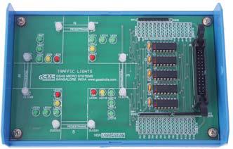
    12. TRAFFIC LIGHTS INTERFACE (MODEL: IF-TRL):

    This interface simulates the control of traffic lights at a traffic island. In each of the four directions (North, South, East, West) LED indicators (Left, Right, Straight, Amber, Red and Pedestrian Red/Green) are provided. These 24 LEDs are controlled through 24 port lines.

    This interface allows user to write software for simulating a variety of traffic situations. Sample programs supplied, will illustrate the traffic movement sequences in a traffic island.

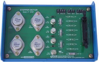
    13. STEPPER MOTR INTERFAC (MODEL: IF-STEP):

    This interface consists of a stepper motor (+12V/+5V DC, 3kg.cm torque), power supply and required driver circuitry along with the necessary software to control the operation of the stepper motor. This interface permits ON/OFF control of the individual coils of the stepper motor at varying speeds in either direction.
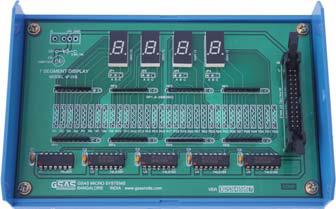
    14. DISPLAY INTERFACE (MODEL: IF-FIDP):

    This interface provides a four digit 7-segment display driven by the output of four cascaded shift registers. Data to be displayed is transmitted serially (bit by bit) to the interface. Each bit is clocked into the shift register by providing a common clock through a port line. Thus one port line provides the data and another port line provides the clock.

    This interface allows the user to study 7-segment display control techniques, code conversion methods etc.The software exercise could include procedures for table look – up, a variety of bit manipulation operations etc..,
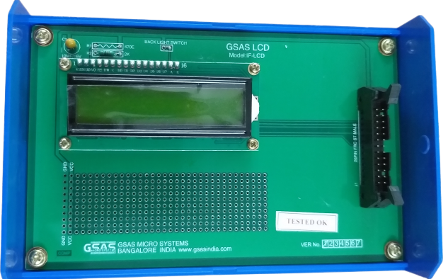
    15. 16×2 LCD INTERFAC WITH BACKLIT (MODEL: IF-LCD):

    LCD modules are widely used in areas where information is conveyed for viewing. They can be seen in calculators, mobile and cellular phones, pagers and other electronic products. The interface is built around 16x2 (Sixteen character per line and two lines) alphanumeric LCD module. This can be directly coupled to any of I/O lines. This present interface module allows the user to become familiar with the techniques of using the LCD module.

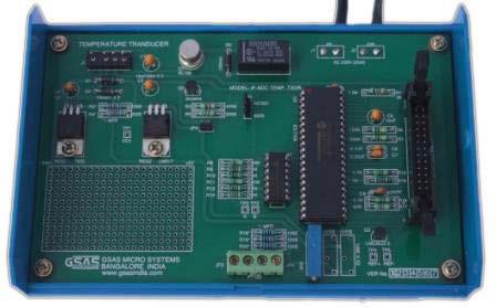
    16. TEMPERATURE TRANSDUCER INTERFACE (MODEL: IF-TXDR):

    This interface is used to control the temperature by interfacing a resistance temperature detector (RTD) with a microprocessor. The RTD converts change in temperature to change in resistance. The change in resistance is converted into change in voltage using a resistance bridge. By using ADC 7109 the voltage is converted into digital form and fed to microprocessor to switch the relay for closed loop operation.

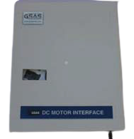
    17. DC MOTOR INTERFACE

    The DC motor used in this interface module is of rating +12V at 250mA. This interface is used to control the speed of the motor. The pulse width modulation technique is used to vary the speed of the DC Motor. The frequency of the pulse is 100HZ keeping the frequency constant, the width of the pulses is used to change the speed .The ramp and pedestal technique is used to change the pulse width and there by the speed. DC motors can be used in various applications like robots, Sewing machines, grinders, lathe, precision high speed drilling and milling spindles.etc.