


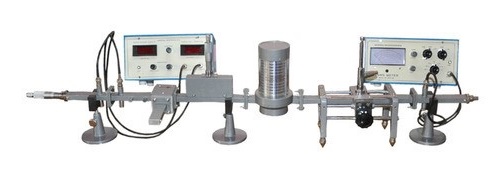
GUNN SOURCE
TEST BENCH KIT MODEL WT 2020 S
KIT CONSISTS OF FOLLOWING COMPONENTS
1. Gunn power supply digital display 1
2. VSWR meter 1
1. Gunn Oscillator 1
2. Pin Modulator 1
3. Isolator 1
4. Slotted line 1
5. Directional coupler 1
6. Magic tee 1
7. S S tuner 1
8. EH tuner 1
9. Tunable probe 1
10. Detector mount 1
11. Variable attenuator 1
12. Horn Pyramidal 2 nos
13. Fixed attenuator 1
14. W/G stands 3 nos
15. Frequency meter 1
16. Reflector sliding termination 1
17. Movable short 1
18. Matched termination 2 nos
19. BNC Cables 3 nos
20. Hardware 1 set
21. Lab manual 1 set
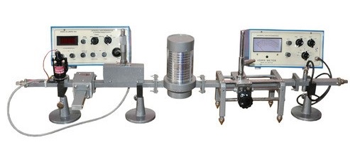
KLYSTRON SOURCE
TEST BENCH KIT MODEL WT 2010 S
KIT CONSISTS OF FOLLOWING COMPONENTS
1. Klystron power supply 1 Nos.
2. VSWR meter 1 Nos.
3. Klystron tube 1 Nos.
4. Klystron mount 1 Nos.
5. Isolator 1 Nos.
6. Slotted line 1 Nos.
7. Tunable probe 1 Nos.
8. Detector mount 1 Nos.
9. Variable attenuator 1 Nos.
10. Directional coupler 1 Nos.
11. Magic tee 1 Nos.
12. SS tuner 1 Nos.
13. EH tuner 1 Nos.
14. Horn parabolic 1 Nos.
15. Reflector Plate 1 Nos.
16. Frequency meter direct reading 1 Nos.
17. Movable short 1 Nos.
18. Matched termination 1 Nos.
19. Waveguide stand 1 Nos.
20. BNC Cables 1 Nos.
21. Hardware 1 Nos.
22. Lab manual 1 Nos.
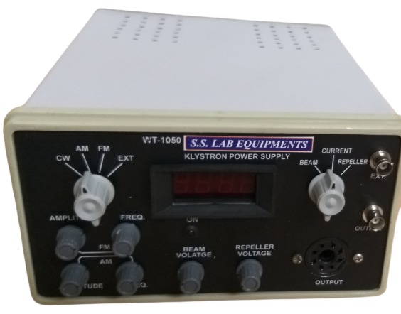
| Operating Voltage | : Mains 230 VAC, 50 Hz |
| Beam Supply | |
| Voltage | : 180-400V (±40V) |
| Current | : 50 mA |
| Regulation | : 0.5% for +/- 10% variation |
| In Power Supply Ripple < 5 mV |
| Repeller Voltage Supply: | |
| Voltage | : 05V TO – 220 (±10V) |
| Regulation | : 0.25%for +/-10% variation in power supply |
| Ripple < 5mv | |
| Filament Supply | : 5VAC |
| Modulation Square | Wave/Saw Tooth |
| Freq | Amplitude |
| AM 50-2500 Hz | 10-15V |
| FM 50-5000 Hz | 10-15V |
| Display | : Digital 3 ½ digit for Beam Supply, Repeller Voltage, beam Current, Standby Switch for Heater |
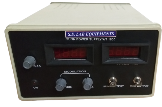
| Operating Voltage | : Mains 230 VAC, 50 Hz |
| Voltage Range | : 0 to 12 Volts Variable (+ 0-12) |
| Regulation | : 0.2% for +/- 10% Variation (mains) |
| Ripple | : 1 mV rms |
| Modulation Square | |
| -Frequency | : 900-2500Hz |
| - Amplitude | : 10-15V Variable |
| Display | : DIGITAL (Separate for Voltage and Current) |
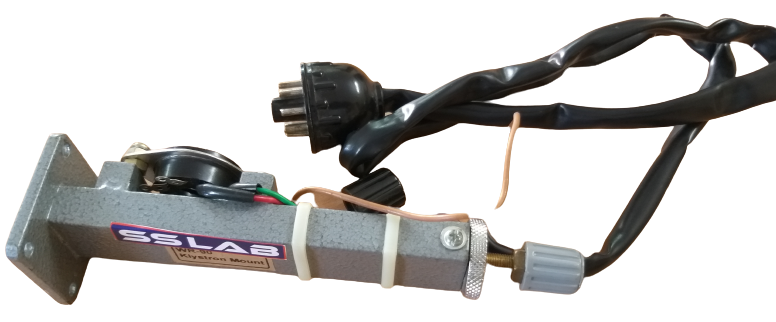
KLYSTRON SOURCE:
It consists of a reflex klystron tube, tube mount in the form of wave-guide cavity & klystron power supply unit.
A small hole in the broad wall of the wave-guide is provided, through which output coupling pin of klystron tube enters into the wave-guide. This hole is exactly located in the center of broad wall because the electric vector of electromagnetic field is maximum at the center ONLY. Maximum
Power is obtained by proper tuning of short matching the impedance of wave-guide to the klystron tube.
Freq |
S |
C |
J |
X |
Waveguide |
WR 284 |
WR 229 |
WR 137 |
WR 90 |
Length( mm) |
240 mm |
190 mm |
170 mm |
130 mm |
Travel |
75 mm |
60 mm |
50 mm |
35 mm |
Power Output |
25 ww |
25 mwatts |
25 mwatts |
25 mwats |
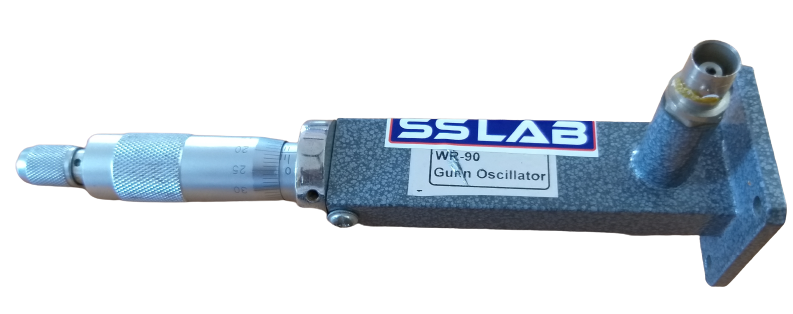
Specifications type while ordering: 1 free running, 2 caviely stabilized, 3 Broadband.
| Band | J |
X |
Ku |
K |
Ka |
Waveguide |
WR 137 |
WR 90 |
WR 62 |
WR 42 |
WR28 |
Model No. |
Go-137-X |
Go-90-X |
GO-62-X |
GO-42-X |
GO-28-X |
Length (mm) |
170 mm |
130 mm |
90 mm |
80 mm |
80 mm |
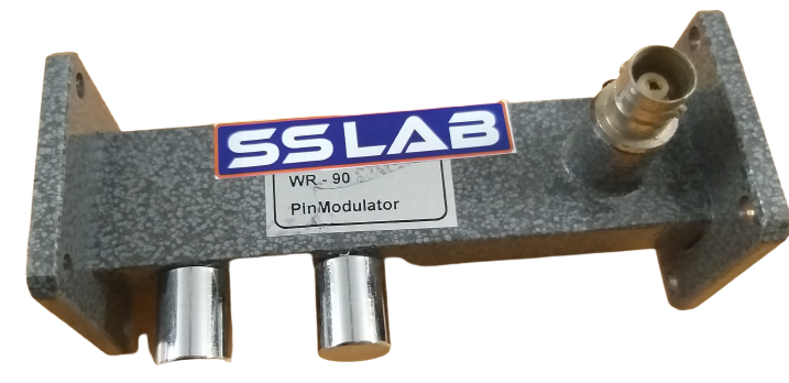
Pin diode used as a switch in wave-guide cavity. Modulation is applied to Pin diode to switch on and off the signals passing thru the wave-guide. Pin Modulator is used to modulate Gunn oscillators. A resistive vane and Taper transformer is used as matching elements.
Frequency Band |
J |
X |
Ku |
K |
Ka |
Waveguide |
WR 137 |
WR 90 |
WR 62 |
WR 42 |
WR 28 |
Model No |
. PM 137 |
PM 90 |
PM 62 |
M 42 |
PM 28 |
Length (mm) |
100 mm |
80 mm |
80 mm |
70 mm |
70 mm |
MAGNETRON SOURCE
WAVETECH also offers magnetron sources at 2.45 GHz with WR 340 Wave-guide output,
Power: 10 watt to 700 watts Waveguide: WR 340 with CPR Flange. RF Source at 1 GHz
Power output: 10 mwatts Output Connector: N (f) Make: Mini Circuits USA.
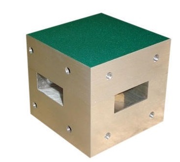
The three port circulator consists of a ferrite prism mounted inside a three port junction and is a D.C. magnetic field provided by a permanent magnet already on the top and bottom of junction. The direction of arrow indicates the direction which the transmission will take without much loss of power. These component works on theory of farraday’s rotation effect in microwave devices.
Circulator are two types T & Y. The difference lies in type of junction whereas the ferrite material is placed with permanent magnet. In T circulator junction is as T type. In Y circulator, junction from 120 degree and it looks in T shape. There are two terms associated with circulator.
(1) ISOLATION: its defined s ration of power in ‘db’ at input part to the isolated part.
(2) INSERTION LOSS: its defined as ration of (db) power at output part to input part.
A three part circulator may be converted into isolator by terminating isolator part by a standard termination.
| BAND | S |
J |
X |
K u |
Ka |
K |
WAVEGUIDE |
WR248 |
WR137 |
WR 90 |
WR 62 |
WR 42 |
WR 28 |
MODEL No Isolation (db) |
XX 284 |
XX 137 |
XX 90 |
XX 62 |
XX 42 |
XX 28 |
Insertion Loss |
20 dB |
20 dB |
20 dB |
20 dB |
20 dB |
0.6 |
(1GHz bandwidth |
0.20.2 |
0.2 |
05 |
08 |
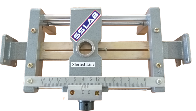
Slotted line consists of a wave guide with a longitudinal narrow slot 2mm on surface of broad wall as at this point, electric vector is maximum leakage of radiation is in very small quantity. The upper most part is know as carriage which can accommodate the tunable detector probe extends the simple and easy methods for finding out the voltage maxima and voltage minima.
After Knowledge of voltage maxima & minima following can be calculated.
(1) Load impendence (2) Standing wave ratio.
(3) Frequency of microwave source at any (4) Reflection co-efficient
Point for dominant made.
(5) Guided wave length
OPTIONAL:
For better accuracy WAVETECH provides dial caliper
To measure accurate siding distance in face shift measurement.
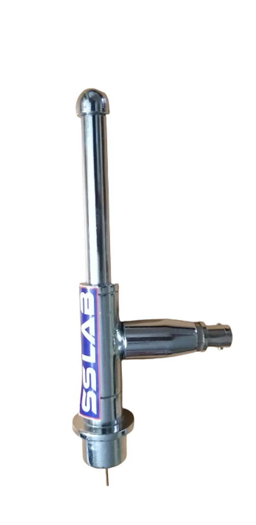
Basically probe is a co-axial line with square law detector. The cavity of probe can be tuned for matching its impedance with slotted line.
The inner conductor of wire penetrated in the wave guide and contact with a detector crystal. The power coupled through inner wire is detected by detector crystal and can measured by any measuring instruments.
In general probe Penetration should be minimum to avoid reflection and distortion in the .
BROADBAND PROBE.
This type of probe is fixed and has no unique part. This probe is suitable full band operation.
WAVETECH also provide a tunable probe in which micrometer fixed on the top of probe for precision work name as precision tunable probe
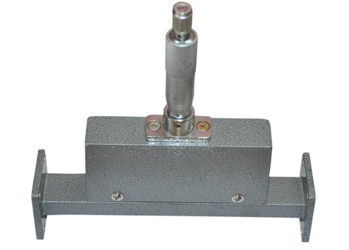
An attenuator is used to reduce power. A resistive vane is used to attenuate signals. The vane is placed in center of broad dimension. The attenuation depends upon depth of Penetration of vane inside of the wave guide.
VARRIABLE ATTENUATOR:
A sliding mechanism is provided to change attenuation. It’s fitted with a precision micrometer. The position of resistive plate can be adjusted up to the accuracy of 0.02 mm. The low V.S.W.R. Of attenuator is maintained by variable and precise range of resistive plate. The value of attenuation is dependant of frequency. These are calibrated at center of band. .
| BAND | S |
C |
J |
X u |
Ku |
K |
Ka |
WAVEGUIDE |
WR 248 |
WR 229 |
WR137 |
WR 90 |
WR 62 |
WR 42 |
WR 28 |
Model No (db) |
WT 284 |
WT 229 |
WT 137 |
WT 90 |
WT 42 |
WT 42 |
WT28 |
Attenuation |
0.02db |
0.02 dB |
0.02 dB |
0.02 dB |
0.02 db |
0.02 db |
0.02 db |
Range (db) |
0-20 |
0-20 |
0-25 |
0-25 |
0-20 |
0-20 |
0-20 |
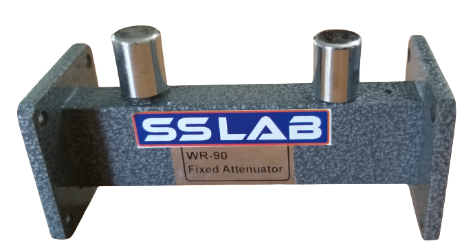
The fixed attenuator reduces power level by a fixed value. These are available in 3 db/6db/10db/ and 20db. The fixed attenuation is calibrated for rated value at the center frequency of narrow band. :
The required amount of attenuation is adjusted changing position of resistive vane with respective to narrow wall .
| BAND | S |
C |
J |
X u |
Ku |
K |
Ka |
Model No |
WR 248 |
WR 229 |
WR137 |
WR 90 |
WR 62 |
WR 42 |
WR 28 |
Model No |
FA 284 -x |
FA 229-x |
FA137-x |
FA 90x |
FA 62-x |
FA-42 -x |
FA 28-x |
Length (mm) |
125mm |
125mm |
100mm |
75mm |
75mm |
75mm |
75mm |
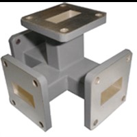
Junction & Tees are required where we split a signal in to 2 or parts in a waveguide system :
E or H-Plane Junction is normally used, available junctions are E-Plane, H-Plane or Magic Tee/Hybrid Tee. .
| FREQ BAND | S |
C |
J |
JX |
X-mil |
Ku |
K |
Ka |
Wave Guide Size |
WR 248 -x |
WR 229 |
WR137 |
WR 90 |
WR112 |
WR 62 |
WR 42 |
WR 28 |
Model No |
DC 284 -x |
DC 229-x |
DC137-x |
DC 90-x |
DC112-x |
DC 62-x |
DC-42-x |
DC 28-x |
Length (mm) |
1140mm |
950mm |
550mm |
350mm |
350mm |
300mm |
250mm |
250mm |
X Stands for coupling value :
Coupling : 3, 6, 10, 20, 30, db .
Directivity : 30db.
VSWR Primary Line….1.1, secondary lane ……1.15 max
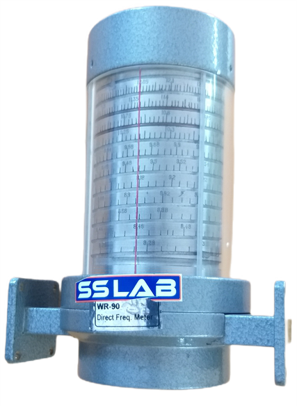
Its used for measuring the frequency of M/W signal in the wave guide system. We use reaction type frequency meter, where a resonant cavity of very high (Q) is coupled to the main waveguide line through a small hole or slot. The movement of plunger is note through cavity is varied by plunger moved by microwave meter or other mechanism. The movement of plunger is noted through the micrometer or can be calibrated as dial of the plunger system. Since the cavity impedance is in series with load, a dip in the load power occurs at the resonant frequency of cavity. The magnitude of dip depends on the value of Q of the cavity. :
The design of cavities such that for a particular position of plunger, the cavity is resonant at a single frequency of away from the resonant frequency of cavity at particular position of plunger. So that transmission is not effected..
SPECIFICATION:
(1) Accuracy: +/- 2 MHz
(2) Calibration increment: 10 MHz
(3) DIP: db at Resonance.
| BAND | S |
C |
J |
X |
Ku |
K |
Ka |
Wave Guide |
WR 248 |
WR 229 |
WR137 |
WR 90 |
WR 62 |
WR 42 |
WR 28 |
Model No |
XX 284 |
XX 229 |
XX 137 |
XX 90 |
XX 62 |
XX 42 |
XX 28 |
DFM- Direct frequency Meter:
FMM – Frequency Meter Micrometer type.
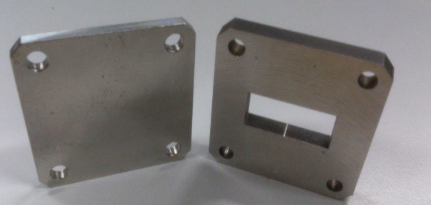
For measurements on slotted line one has to use wave guide shorts as Reference.
Both fixed plate and movable precision shorts are available:
| FREQ | S |
C |
J |
X |
Ku |
K |
Ka |
Wave Guide Size |
WR 248 |
WR 229 |
WR137 |
WR 90 |
WR 62 |
WR 42 |
WR 28 |
Model No |
XX 284 |
XX 229 |
XX 137 |
XX 90 |
XX 62 |
XX 42 |
XX 28 |
Length (mm) |
240 |
190 |
170 |
130 |
75 |
75 |
75 |
SP… Movable Short Precision with micrometer :
MS... Movable Short Ordinary .
FS… Fixed short.
RF.... Reflector Short (Flange).
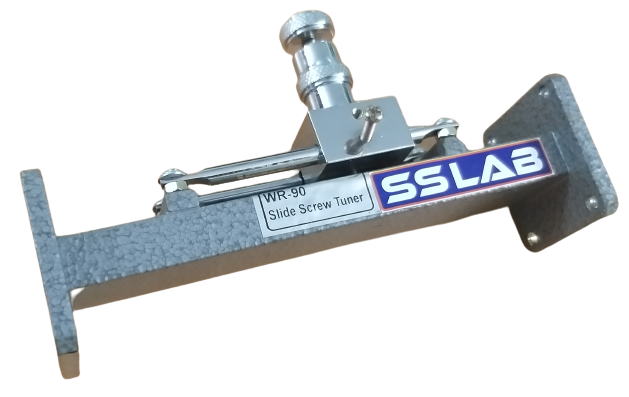
Microwave tuners are meant for matching the transmission line with load. This helps in keeping the .
VSRW low. The line is properly matched when the load impedance equals to characteristic impedance of line .
To achieve this either resistive or reactive components is used. The value of resistive component will be free from change of frequency but definitely introduces some loss. The reactive components are subject to change with frequency but are loss less
.
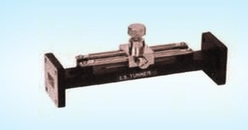
SLIDING SCREQ TUNERS
This consists of a screw whose penetrations in wave guide can be adjusted it is mounted on a carriage. This carriage along with screw can move over the main wave guide (board band) m longitudinal position of carriage the screw cane be precisely penetrated up to desired depth. This type of turner has effect of shunt capacitance up to ¼ depth and onward ¼ depth the effect will be inductive:
EH-TUNERS:
E-H Tuners is combination of movable tuner and E-H Tee. E-Tee has E and H arms provided with movable shorting plunger. The reactance presented by H and E depends on the position of respective short circulating plunger in the two arms. The reactance inserted by EM tuner is adjustable over wide range. Since there is no slot or opening, there is less power loss:
| FREQ | S |
C |
J |
X |
Ku |
K |
Ka |
Wave Guide |
WR 248 |
WR 229 |
WR137 |
WR 90 |
WR 62 |
WR 42 |
WR 28 |
Model No |
XX 284X |
XX 229 X |
XX 137 X |
XX 90X |
XX 62X |
XX 42 X |
XX 28X |
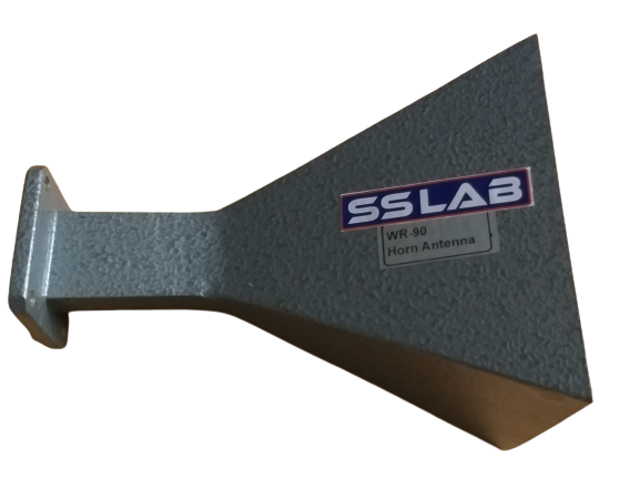
STANDARD GAIN HORN ANTENNA:
These are various type of horn antenna such as sectorial and circular horn. We are manufacturing Pyramidal horn only and it can be used as transmission and receiver antenna. The directional properties Of the antenna are represented in terms of radiation pattern and gain of horn. The radiation intensity in a
given direction is the power radiation from horn per unit solid angle in that direction and radiation efficiency is the ration of the power radiated to the total power supplied to the horn ex. Power gain in a given direction is the times the ratio of radiation intensity ion the direction to the power delivered to horn.
:
| FREQ | S |
C |
J |
X |
Ku |
K |
Ka |
Wave Guide |
WR 248 |
WR 229 |
WR137 |
WR 90 |
WR 62 |
WR 42 |
WR 28 |
Model No |
XX 284 |
XX 229 |
XX 137 |
XX 90 |
XX 62 |
XX 42 |
XX 28 |
DIELECTRIC::
These are basically sample holder cavities to hold samples for dielectric measurement, Both solid and liquid dielectric cells are available where distance of sample can be varied relative to slotted line:
| FREQ | S |
C |
J |
X |
Ku |
K |
Ka |
Wave Guide |
WR 248 |
WR 229 |
WR137 |
WR 90 |
WR 62 |
WR 42 |
WR 28 |
Model No |
XX 284 |
XX 229 |
XX 137 |
XX 90 |
XX 62 |
XX 42 |
XX 28 |
SDC---Solid dielectric cell movable plunger:
SDH---Solid dielectric sample holder fixed
LDC--- Liquid dielectric cell with movable plunger
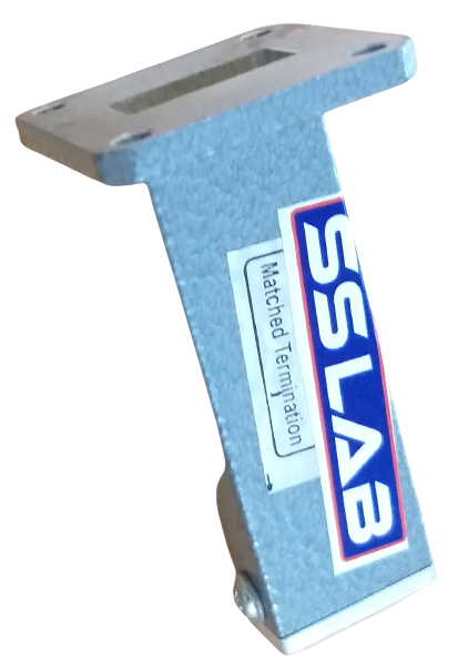
DUMMY LOADS:
WAVETECH standard products line of high and low terminations are constructed using extruded Heat sink material. The load elements are custom ground silicon carbide Tapered for optimum Response (1.15 max) maintaining moderate power handling characteristics.
| FREQ BAND | S |
C |
J |
X |
Ku |
K |
Ka |
Wave Guide |
WR 248 |
WR 229 |
WR137 |
WR 90 |
WR 62 |
WR 42 |
WR 28 |
Length (mm) |
200 mm |
200 mm |
200 mm |
125 mm |
100 mm |
50 mm |
50 mm |
VSWR Max |
1.06 |
1.06 |
1.06 |
1.06 |
1.08 |
1.08 |
1.08 |
Max Power |
100 watts |
100 watts |
10 watts |
10 watts |
5 watts |
2 watts |
1 watts |
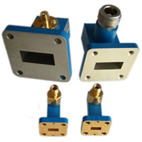
WAVEGUIDE TO COAXIAL ADAPTER:
This is immense to collect waveguide output to coaxial system. The waveguide made is converted to TEM coaxial mode. The output connector can be N type or SMA type. Low VSWR is maintained for optimum Coupling.
| FREQ BAND | S |
C |
J |
X |
Ku |
K |
Ka |
Wave Guide |
WR 248 |
WR 229 |
WR137 |
WR 90 |
WR 62 |
WR 42 |
WR 28 |
Model No |
XX 284 |
XX 229 |
XX 137 |
XX 90 |
XX 62 |
XX 42 |
XX 42 |
VSWR Max |
1.25 |
1.25 |
1.25 |
1.25 |
1.25 |
1.25 |
1.25 |
Max Power |
100 mm |
75 mm |
50 mm |
30 mm |
Custom |
Custom |
Custom |

MULTI HOLE DIRECTIONAL COUPLER:
Directional couplers are used to sample power flowing in waveguides. The power so tapped is Called coupling factor or coupling in db, of directional coupler. These are designed using microwave CAD software’s. These are available in 3, 6, 10 and 20 db coupling. It consists of two waveguide, joined with there broad wall. The main wave guide is straight and fitted with flanges at both ends. The auxiliary wave guide has 90° bend at one in E plane and another end is fitted with suitable matched load. The common broad wall of bath wave guides has a row of coupling hoes. The diameter and no of holes in a row and no of row varies accordingly to coupling factor require.
.
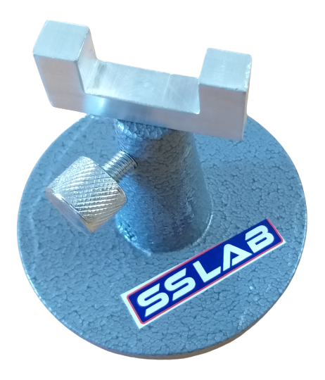
WAVEGUIDES STAND.
Universal waveguide stand for waveguide bands. The stands are adjustable in height and can be locked in any position by means of a screw to hold the waveguide system horizontally. For any bench set 4 to 5 Nos may be used to keep otherwise problem may raise to keep the system horizontally..
.
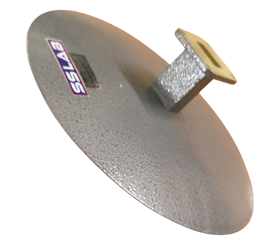
PARABOLIC ANTENNA
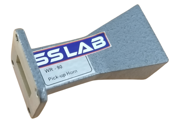
HORN ANTENNA