loader

ARM 9

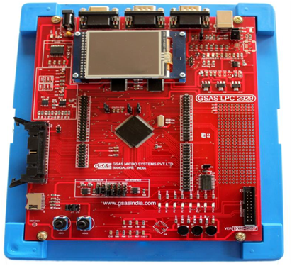
LPC 2929 is an evaluation board for the NXP LPC 29xx microcontroller family. LPC 2929 allows the user to evaluate the capabilities of the NXP LPC 29xx and create real working environment with KEIL development tools. The LPC 2929 is supplied with the NXP LPC 2929 the superset of several other device variants of the NXP LPC 29xx controller

LPC 2929 is powered by USB port. A serial connection is provided for In-System-Programming and it provides Serial (RS-232), CAN and USB interfaces as well as 8 LEDs, analog input (via potentiometer) and three switches. On-board JTAG connector is provided for connecting JTAG based debuggers like KEIL ULINK, SEGGER J-LINK, etc.,

On board power supply connector and 26 pin FRC connector are available for interfacing the GSAS LPC 2929 board to some of the Interface Modules such as Seven Segment Display, Elevator, Traffic Lights, Dual DAC, Txdr ADC etc., enables the user to develop and debug code for the GSAS interface modules.
MAIN FEATURES
  • • LPC 2929 is powered by PC’s USB port.
  • • LPC 2929 communicates with host PC through its on-board serial ports – Rs 232C/USB.
  • • On-chip 768K bytes Flash,56kBytes RAM and 16k Bytes EEPROMs are available to user.
  • • One No. of on chip UART port COM0 is terminated on 9 pin D type (Female) connector P1.
  • • Provision for CAN interface (CAN0 and CAN1 are terminated on two 9 Pin D type (male) connectors P2 and P3.
  • • USB interface uses the standard USB connector type-B for the full speed USB 2.0 peripheral of LPC 2929 device.
  • • SD card connector that supports a wide range of memory cards.
  • • Provision for two LIN interfaces.
  • • The status of the port lines P2.16 to P2.23 can be monitored through 8 on board LED’s.
  • • Provision for USB-OTG connector is available for the full speed USB 2.0.(Type-B)
  • • Color QVGA TFT LCD for the user interface.
  • • On board RESET switch and S1(P2.26), S2(P2.27) switches for INT.
  • • Provision for 5 position Joystick .
  • • Two on-chip analog voltage regulators to feed analog input to ADC.
  • • The prototyping area along with +5V,+3.3V,+1.8V and GND points.
  • • Flexible configuration using jumpers.
  • • On-chip I2C and SPI interfaces are available to the user
SPCIFICATIONS
  • MCU :NXP LPC 2929
  • MCU clock :125 Mhz
  • On-chip RAM :56KB
  • On-chip Flash :768KB
  • Serial Ports :1(On-chip)
  • CAN Ports :2(On-chip)
  • USB Interface :1(On-chip)
  • PCB Size :170 X 202 mm
  • JTAG Interface :20 Pin standard IDC connector
  • Power connector :Standard USB Type -B connector
  • 1. LPC 2929 Evaluation board
  • 2. USB Cable
  • 3. Driver software CD
  • 4. User manual

8051 Embedded

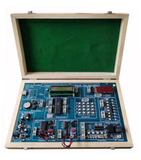
Technical Specification:-
  • • 8 bit microcontroller P89V51RD2 which operates at 11.0592 MHz frequency.
  • • LED and switch interface.
  • • LCD Display (16x2).
  • • 4 Seven segment display
  • • Hex keyboard (4x4 matrix) for calculator Display o/p on LCD or seven segments.
  • • ADC 0808/09 and temp controller interface.
  • • Generation of different wave Form sine, square, triangular, ramp etc, using DAC.
  • • Stepper motor and DC motor control interface.
  • • EEPROM Interface.
  • • DS1307, Real Time Clock (RTC) with battery backup (i2c).
  • • Elevator with 8 floors.
  • • Serial communication between P.C. and 8051.
  • • Buzzer interface
  • • Good quality PCB Glass epoxy FR4 material
  • • On board ground test point for testing and connecting CRO.
  • • Power ON LED indication for +ve and –Ve supply.
  • • On board –Ve voltage generator.
  • • All IC’s on socket so easy serviceable.
  • • External power supply connection facility
  • • On board Regulator
  • • In case of service by removing 4 screws board easily removable.
  • • Board is easy to understand so can be used for project development

AVR Development Trainer

Technical Specification:-
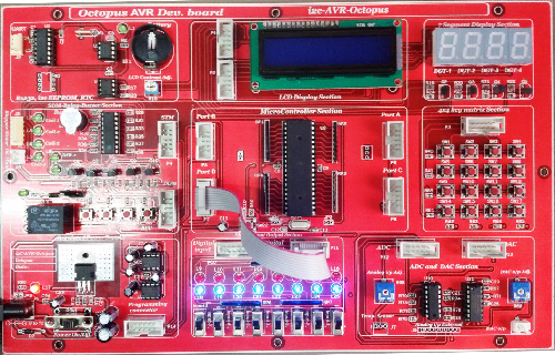
    The I2C-AVR Octopus board consists:
  • 8 bit microcontroller ATmega32 which operates at 16MHz frequency.
  • RS232 Serial Interface and ISP/IAP flash programming.
  • 2 Lines X 16 Character LCD Display.
  • 4 Seven segment display (common anode).
  • 4 X 4 Matrix keyboard.
  • On chip 8-channel, 10-bit ADC (Analog to Digital Converter).
  • DAC0800, 8 Bit Digital to Analog Converter.
  • Stepper motor driver circuit.
  • DC motor driver circuit.
  • 24C16, Serial EEPROM chip (i2c).
  • DS1307, Real Time Clock (RTC) with battery backup.
  • Buzzer interface.
  • Relay interface
  • 8-LED and 8-switch interface.
  • Onboard hardware reset.
Features of ATmega32:-
  • • High-performance, Low-power AVR® 8-bit Microcontroller.
  • • Advanced RISC Architecture.
  • • Nonvolatile Program and Data Memories.
  • • 32K Bytes of In-System Self-Programmable Flash
  • • Optional Boot Code Section with Independent Lock Bits.
  • • 1024 Bytes EEPROM.
  • • 2K Byte Internal SRAM.
  • • JTAG (IEEE std. 1149.1 Compliant) Interface.
  • • Two 8-bit Timer/Counters with Separate Presales and Compare Modes.
  • • One 16-bit Timer/Counter with Separate Prescaler, Compare Mode, and Capture Mode.
  • • Real Time Counter with Separate Oscillator.
  • • Four PWM Channels
  • • 8-channel, 10-bit ADC.
  • • Programmable Serial USART.
  • • Power-on Reset and Programmable Brown-out Detection.
  • • External and Internal Interrupt Sources
  • • Six Sleep Modes: Idle, ADC Noise Reduction, Power-save, Power-down, Standby and Extended Standby.
  • • 32 Programmable I/O Lines.
  • • 0 - 16 MHz for ATmega32.

ARM7_spec_1- Titel _ ARM-7

1. Embedded Dev ARM LPC2148 “iem-201-Machu” Board is a evaluation board for LPC2148 ARM7TMDI based microcontroller.

2. The LPC2148 microcontroller has 512KB of internal flash and 32+8K RAM.

3. Following are the salient features of the board.

  • • Dimensions: 295x190 mm
  • • Power: On Board 5V, 3.3V & -5V DC power supply with LED Indication.
  • • USB connector (as alternate power source).
  • • Connectors:
    UART0 & UART1 connectors
    VGA connector
    PS/2 connector
    JTAG connector
    SD/MMC connector
    USB B-type connector with Link-LED
    3.5mm Audio Jack with power amplifier
    256Kb I2C based EEPROM
    PWM output with two LED’s
4. Other Peripherals:
  • • UART0 is used for download the HEX file and UART1 also provide for serial communication with RESET and ISP switch.
  • • 16X2 character LCD with back light control.
  • • 128X64 GRAPHICS LCD.
  • • Configurable for manual and automatic program download (ISP) via serial port.
  • • 4 seven segment display(common anode)
  • • DC Motor interface with speed and direction control.
  • • Stepper Motor interface with speed and direction control.
  • • 8 LED interface.
  • • DAC OUTPUT with externally variable amplitude using pot.
  • • ADC with Temp. Sensor and provision of variable analog input via 10k pot.
  • • Externally ADC using SPI.
  • • BUZZER interfacing.
  • • RELAY Interfacing.
  • • Use On chip RTC with battery backup.